
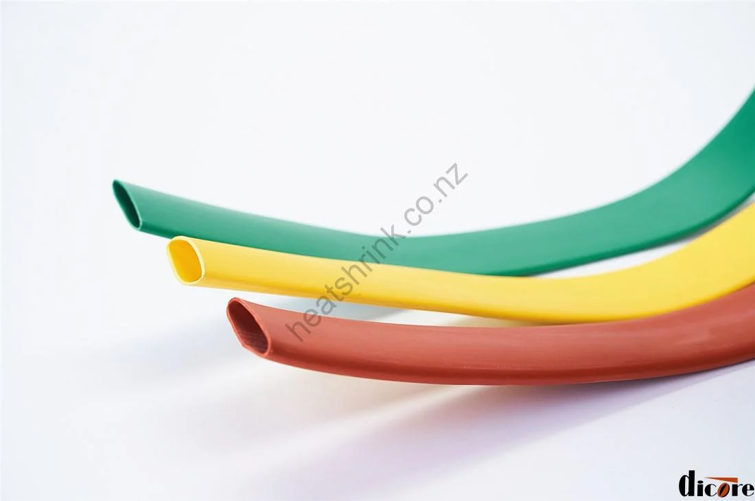


Model: HBBT
High Voltage Heat Shrink Busbar Insulation Tubing (HBBT)
Dicore HBBT series busbar heat shrink tubing provides superior electrical insulation, tracking resistance, and flashover protection for copper and aluminum busbars. Designed for low to high voltage switchgear and substations (up to 35kV), it significantly reduces phase-to-phase clearance requirements while protecting against accidental contact and wildlife interference.
Key Features & Benefits
- Voltage Ratings Available: 1kV, 10kV, 20kV, and 35kV rating options to meet diverse switchgear and transformer insulation demands.
- Compact Switchgear Design: Reduces physical clearance requirements between busbars, allowing engineers to build smaller, space-efficient switchboards.
- Wildlife & Accidental Contact Protection: Prevents short circuits caused by small animals (rodents, birds) and accidental human contact during maintenance.
- Corrosion & Tracking Resistance: High resistance to tracking, arcing, and aggressive chemicals (acids, alkalis, and salts).
- Flexible Installation: Supplied in continuous lengths for cost-effective cutting and simple installation using heat guns or gas torches.
Common Applications
- Switchgear and substation busbar insulation
- Bus duct assemblies and power distribution cabinets
- High and low voltage transformer installations
- Industrial electrical equipment protection in harsh environments
Product Specifications & Technical Data
Model: HBBT
Available Colors: Red, Green, Yellow, Black (Other colors available on request)
Technical Properties
| Item | Test Method | Value |
|---|---|---|
| Tensile Strength | ASTM D 2671 | ≥ 8 Mpa |
| Elongation at Break | ASTM D 2671 | ≥ 300% |
| Tensile Strength After Aging (130°C x 168h) | – | ≥ 6.9 Mpa |
| Elongation at Break After Aging (130°C x 168h) | – | ≥ 100% |
| Longitudinal Shrinkage | ASTM D 2671 | -8% ~ 8% |
| Oxygen Index | GB/T 2406 | ≥ 27 |
| Heat Shock | JB7829 D | No Crack |
| Breakdown Strength | ASTM 3 149 | ≥ 20 KV/mm |
| Rigidity (Shore A) | GB 2411 | ≤ 90 |
| Volume Resistivity | IEC 60093 | 1014 Ω·cm |
1KV Specification
| Size (mm) | As Supplied (mm) | After Recovery (mm) | Packing (m/roll) | |
|---|---|---|---|---|
| I.D. | I.D. (max) | W.T. | ||
| 30 | 31.5 ± 1.0 | 15.0 | 1.0 ± 0.15 | 50 |
| 35 | 36.5 ± 1.0 | 17.5 | 1.0 ± 0.15 | 50 |
| 40 | 41.5 ± 1.0 | 20.0 | 1.0 ± 0.15 | 50 |
| 50 | ≥ 50 | 25.0 | 1.1 ± 0.15 | 25 |
| 60 | ≥ 60 | 30.0 | 1.2 ± 0.15 | 25 |
| 70 | ≥ 70 | 35.0 | 1.3 ± 0.15 | 25 |
| 80 | ≥ 80 | 40.0 | 1.3 ± 0.20 | 25 |
| 90 | ≥ 90 | 45.0 | 1.3 ± 0.20 | 25 |
| 100 | ≥ 100 | 50.0 | 1.3 ± 0.20 | 25 |
| 120 | ≥ 120 | 60.0 | 1.3 ± 0.20 | 25 |
| 150 | ≥ 150 | 75.0 | 1.3 ± 0.20 | 25 |
| 180 | ≥ 180 | 90.0 | 1.3 ± 0.20 | 25 |
| 210 | ≥ 210 | 105.0 | 1.3 ± 0.30 | 25 |
| 230 | ≥ 230 | 115.0 | 1.3 ± 0.30 | 25 |
| 250 | ≥ 250 | 125.0 | 1.3 ± 0.30 | 25 |
| 300 | ≥ 300 | 150.0 | 1.3 ± 0.30 | 25 |
10KV Specification
| Size (mm) | As Supplied (mm) | After Recovery (mm) | Packing (m/roll) | |
|---|---|---|---|---|
| I.D. | I.D. (max) | W.T. | ||
| 15 | 15 ± 0.8 | ≤ 8 | 2.10 ± 0.30 | 25 |
| 20 | 20 ± 0.8 | ≤ 10 | 2.10 ± 0.30 | 25 |
| 25 | 25 ± 0.8 | ≤ 12 | 2.10 ± 0.30 | 25 |
| 30 | 30 ± 0.8 | ≤ 15 | 2.10 ± 0.30 | 25 |
| 40 | 40 ± 1.0 | ≤ 20 | 2.30 ± 0.30 | 25 |
| 50 | 50 ± 2.0 | ≤ 25 | 2.30 ± 0.30 | 25 |
| 60 | 60 ± 3.0 | ≤ 30 | 2.30 ± 0.30 | 25 |
| 70 | 70 ± 3.0 | ≤ 35 | 2.30 ± 0.30 | 25 |
| 80 | 80 ± 3.0 | ≤ 40 | 2.30 ± 0.30 | 25 |
| 100 | 100 ± 4.0 | ≤ 50 | 2.40 ± 0.30 | 25 |
| 120 | 120 ± 4.0 | ≤ 60 | 2.40 ± 0.30 | 25 |
| 150 | 150 ± 4.0 | ≤ 75 | 2.40 ± 0.30 | 25 |
| 180 | 180 ± 5.0 | ≤ 90 | 2.40 ± 0.30 | 25 |
| 210 | 210 ± 5.0 | ≤ 105 | 2.40 ± 0.30 | 20 |
| 230 | 230 ± 5.0 | ≤ 115 | 2.40 ± 0.30 | 20 |
| 250 | 250 ± 5.0 | ≤ 125 | 2.40 ± 0.30 | 20 |
| 300 | 300 ± 5.0 | ≤ 150 | 2.40 ± 0.30 | 15 |
20KV Specification
| Size (mm) | As Supplied (mm) | After Recovery (mm) | Packing (m/roll) | |
|---|---|---|---|---|
| I.D. | I.D. (max) | W.T. | ||
| 15 | 15 ± 0.8 | ≤ 8 | 2.50 ± 0.20 | 20 |
| 20 | 20 ± 0.8 | ≤ 10 | 2.50 ± 0.20 | 20 |
| 25 | 25 ± 0.8 | ≤ 13 | 2.50 ± 0.20 | 20 |
| 30 | 30 ± 0.8 | ≤ 15 | 2.50 ± 0.20 | 20 |
| 40 | 40 ± 1.0 | ≤ 20 | 2.80 ± 0.30 | 25 |
| 50 | 50 ± 2.0 | ≤ 25 | 2.80 ± 0.30 | 25 |
| 60 | 60 ± 3.0 | ≤ 30 | 2.80 ± 0.30 | 25 |
| 70 | 70 ± 3.0 | ≤ 35 | 2.80 ± 0.30 | 25 |
| 80 | 80 ± 3.0 | ≤ 40 | 2.80 ± 0.30 | 25 |
| 100 | 100 ± 4.0 | ≤ 50 | 2.80 ± 0.30 | 25 |
| 120 | 120 ± 4.0 | ≤ 60 | 2.80 ± 0.30 | 25 |
| 150 | 150 ± 4.0 | ≤ 75 | 2.80 ± 0.30 | 25 |
| 180 | 180 ± 5.0 | ≤ 90 | 2.80 ± 0.30 | 25 |
| 210 | 210 ± 5.0 | ≤ 105 | 2.80 ± 0.30 | 20 |
| 230 | 230 ± 5.0 | ≤ 115 | 2.80 ± 0.30 | 20 |
35KV Specification
| Size (mm) | As Supplied (mm) | After Recovery (mm) | Packing (m/roll) | |
|---|---|---|---|---|
| I.D. | I.D. (max) | W.T. | ||
| 30 | 30 ± 1.0 | ≤ 15.0 | 4.00 ± 0.30 | 15 |
| 40 | 40 ± 1.0 | ≤ 20.0 | 4.00 ± 0.30 | 15 |
| 50 | 50 ± 2.0 | ≤ 25.0 | 4.00 ± 0.30 | 15 |
| 60 | 60 ± 2.0 | ≤ 30.0 | 4.00 ± 0.30 | 15 |
| 70 | 70 ± 2.0 | ≤ 35.0 | 4.00 ± 0.30 | 15 |
| 80 | 80 ± 4.0 | ≤ 40.0 | 4.00 ± 0.30 | 15 |
| 100 | 100 ± 4.0 | ≤ 50.0 | 4.00 ± 0.30 | 15 |
| 120 | 120 ± 4.0 | ≤ 60.0 | 4.00 ± 0.30 | 15 |
| 150 | 150 ± 4.0 | ≤ 75.0 | 4.00 ± 0.30 | 15 |
| 180 | 180 ± 5.0 | ≤ 90.0 | 4.00 ± 0.30 | 15 |
| 210 | 210 ± 5.0 | ≤ 105.0 | 4.00 ± 0.30 | 15 |
| 230 | 230 ± 5.0 | ≤ 115.0 | 4.00 ± 0.30 | 15 |
| 250 | 250 ± 5.0 | ≤ 125.0 | 4.00 ± 0.30 | 15 |
| 300 | 300 ± 5.0 | ≤ 150.0 | 4.00 ± 0.30 | 15 |
Frequently Asked Questions (FAQ)
Q: How do I choose between 1kV, 10kV, 20kV, and 35kV busbar tubing?
A: Selection depends on the operating voltage of your switchgear or substation system. The wall thickness (W.T.) increases with higher voltage ratings to ensure adequate dielectric strength and tracking resistance.
Q: Can busbar heat shrink tubing be used on curved or bent busbars?
A: Yes, the tubing is highly flexible and shrinks uniformly over bends, right angles, and irregular copper/aluminum profiles without splitting.
Q: Does Dicore supply custom colors or cut lengths in New Zealand?
A: We supply continuous rolls in standard phase colors (Red, Yellow, Green, Black). Custom colors, specific sizes, and bulk project orders can be provided upon request with fast local dispatch within New Zealand.
Q: How do I select the correct tubing size for my rectangular busbar?
A: Since busbars have a rectangular cross-section while heat shrink tubing is circular, you need to calculate the equivalent size to ensure a tight, void-free fit. We recommend using one of the following two methods:
Method 1: Diagonal Calculation (Recommended)
1. Measure the width (W) and thickness (T) of your busbar.
2. Calculate the diagonal length of the cross-section: Diagonal = √(W² + T²)
3. Check the “After Recovery I.D. (Max)” column in our specification table. Choose a tubing size where this value is larger than your calculated diagonal.
4. Important: Also verify that the “As Supplied I.D.” is large enough for the tubing to slide over the busbar easily before heating.
Method 2: Perimeter Calculation
1. Calculate the perimeter of the busbar: Perimeter = 2 × (Width + Thickness)
2. Calculate the equivalent circular diameter: Diameter = Perimeter ÷ 3.14 (π)
3. Select a tubing size with an “After Recovery I.D. (Max)” greater than this equivalent diameter.
Practical Example:
For a busbar measuring 50mm (Width) × 5mm (Thickness):
– Diagonal = √(50² + 5²) = √2525 ≈ 50.2mm
– You need tubing with an “After Recovery I.D. (Max)” greater than 50.2mm.
– Looking at the 10kV specification table, Size 100 recovers to ≤50.0mm (which would be too tight). Therefore, you should choose the next size up: Size 120 (which recovers to ≤60.0mm), ensuring a perfect, stress-free fit.
Rule of Thumb: Always choose the next size up if your calculation falls exactly on or between two standard recovered I.D. sizes. This ensures easier installation and prevents over-stretching the tubing material.